The insertable toy was the first one I thought of over a year ago. The original design involved wires and conductive paint to somehow create capacitive touch surfaces.
I knew that wouldn’t work, not least because the exposed wires were not going to be a smart idea in the butt. With the discovery of the conductive silicone I decided that maybe the best approach would be to pour layer after layer of conductive and non-conductive silicone into a negative mold of a penis but that just created more questions, namely: how do I get the wires connected to the conductive silicone in the first place?

I thought about having a solid center with conductive pads on it for the shaft, the benefit of that approach would be that I could put batteries in it and such. Advice from my friends who have far more experience with toys of this nature quickly scrapped that idea, but not before I got a nice 3D model printed.
The design above and model to the right is of a 20mm diameter shaft with a 18mm hollow that could accept 2 AA batteries and go inside a toy. The consensus from my friends who have more experience with butt toys was that if you’re making a silicone toy, you may as well have as much of it silicone as possible.
It was as I was fiddling with some CAT 5 networking cable that I had the brilliant idea: hey, I could just stick this up your butt! The design changes from a 20 mm solid core to a flexible core about 9 mm in diameter, but how to make the layers of conductive and non conductive silicone.

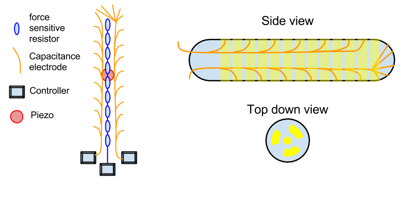
I had already determined that 5 – 10 mm of non conductive silicone would be a perfect protection from the conductive silicone whilst keeping the capacitance. 20 mm made sense then as the insulating distance between layers. What I needed then was a shaft that looked like this.
As you can see, I split the conductive silicone into two “hemispheres” to allow for more accurate sensing of what is going on.
How then, do I get such accurate layers? Well one of my lessons from before is that silicone is best when worked additively. That is to say: adding more silicone to silicone is easy, taking it away is hard. I also learnt that pouring silicone in layers sucks.
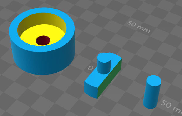
I decided to use a mold which would allow me to create little cylinders of silicone which I could then glue together with more silicone. Behold the new design above/right. It’s made of three pieces: “O” on the left, “T” in the middle and “I” on the right.

The mechanical connections are very chunky and simple, which works best for 3D printed parts. the “T” shaped piece goes into the “O” cylinder mold first, allowing you to create the two hemispheres. I found that using cling wrap on top allowed me to get a “clean” finish to the top of the layers. Also note that the conductive silicone is pretty “hairy”. I cute those hairs off easily with a pair of scissors.
Once the two hemispheres are set, you replace the “T” with the “I”, which then leaves the negative space for the non-conductive silicone parts:

With the “I” piece in, the molds can also be used to make the non-conductive rings:

Putting it all together is relatively simple thanks to silicone’s ability to bond at a molecular level with other silicone. The “I” pieces were a convenient way to keep the pieces aligned so that they would set properly.


I tried cutting some CAT 5 cable so that I could insert that into the conductive layers, but that ended in disaster. My wire stripping skills and the need for accurate measurements meant that the wires just weren’t the right length, and I was never going to be able to stick them into the silicone with any degree of consistency, even after “tinning” the stranded wire with solder.
In the end, I used solid core wire rather than stranded wire. Solid wire sticks better into the conductive silicone anyway.
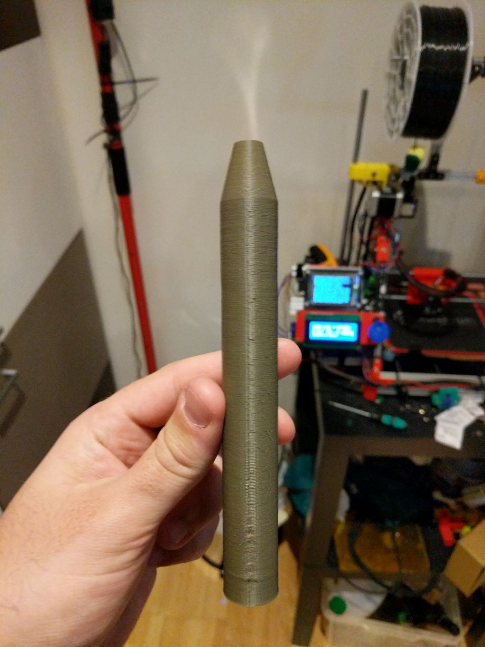
Click here to see the completed insertable prototype.
Things I learnt from this exercise:
- It’s easier to cut small slivers of silicone with scissors
- It’s easier to cut conductive silicone than non-conductive
- Cling wrap is good for getting “clean” edges with silicone
- You need something to keep the models aligned when gluing them together (in this case the “I” pieces)
- CAT 5 cable is stranded wire so not best for sticking into silicone.
2 comments