So, I have gesture detection working relatively well, the next hurdle is speed of the gesture. It sounds like a relatively simple problem to solve, but it’s deceptively complex, especially since we’re dealing with a series of data points.
In the video above, I am using a simple moving average on stream 3 of the input. Whenever the current data point drops below the moving average, that’s considered an “out”, when it drops above, that’s considered an “in”, the result is data that looks something like this:
Every time the blue line crosses the yellow line, we count a “tick”. Speed is the number of ticks in the last 16 samples.
Whenever the data value crosses the moving average in any direction, I consider that a “tick”. I then count the number of ticks in the last n samples to get an average speed during those samples.
It works surprisingly well, you could increase the number of samples to get a smoother speed calculation, but I think a responsive value is better. I am currently summing across 16 ticks.
In theory, a Fast Fourier Transform should be able to give me the frequency of the signal I am recording and that frequency could be used to approximate speed of the “hand job” gesture. In practice, I think the moving average approach is relatively computationally cheap as well as robust.
I am pleased to report that the stream of data I have been collecting off the insertable device can be used to detect different user gestures. Gestures you ask? Well, I want to be able to tell what the user is doing with the device (e.g. blowjob, licking, hand job and penetrative buttsex). Not sure if I can tell the difference between a vagina and a butt, but why not try?
The video below shows the device distinguishing between blow jobs and hand jobs.
Dynamic Time Warping (or DTW) is a great little solution for matching time-series data where the data points might be stretched or squashed over time. Apart from detecting blow jobs it has been used for speech recognition among other things.
I retrieve the stream of 8 data points from the device, let’s call a collection of these 8 data points a set. I get a set every 100 ms. When I have more than 8 sets of data, I attempt to match those 8 sets of 8 data points to a prerecorded “example” sequence of 32 sets in memory using the Dynamic Time Warping algorithm.
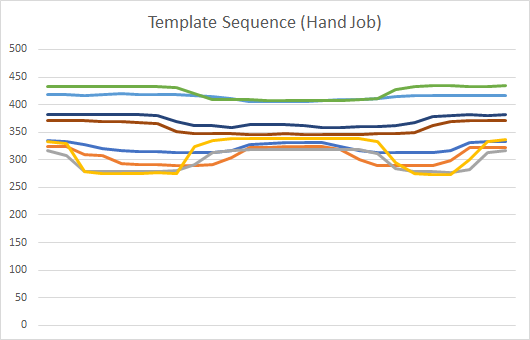
The image below is an example sequence of a “hand job” gesture:
Template sequence used to determine if a gesture is a hand job.
Because lube and other environmental factors can change the baseline considerably, I “normalise” the data to a value from 0 to 1 for each independent stream (line) of data. This seems to be a pretty robust approach.
Template sequence normalised to remove bias due to environmental factors. .
Normalising in this way is helpful, especially if you consider that the conductive silicone will also have a capacitance and due to my imperfect construction process, I can’t guarantee this will be consistent in any way.
A last step (which I haven’t yet tried but will shortly) is to apply a simple moving average to smooth the data out. This should result in more reliable matches.
The normalised sequence is smoothed to allow for more reliable detection.
I have been able to get this same algorithm working in C# as well as Renpy, a Python based gaming engine I intend to use for a game that interacts with the device. Unfortunately Renpy is a little too slow for the processing and is not really designed for this kind of real-time processing anyway.
Next step: move the gesture recognition processing onto the arduino itself for performance reasons. Turns out there’s not enough memory to implement a DTW algorithm for more than one gesture on an arduino. Never mind, I learnt how to do threads in Renpy instead (renpy.invoke_in_thread).
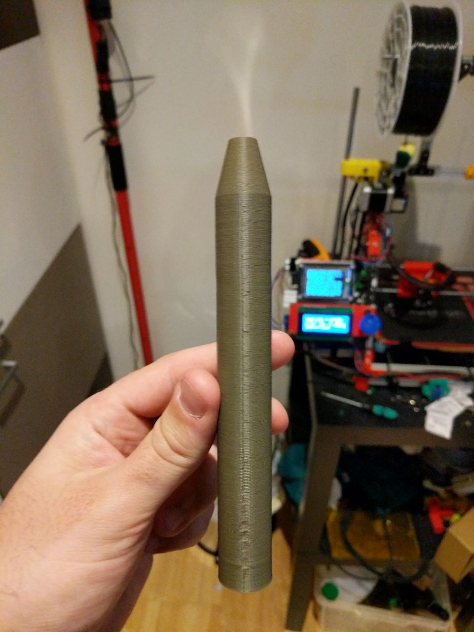
So, here we are, the moment you have all been waiting for: behold a working prototype of an insertable toy.
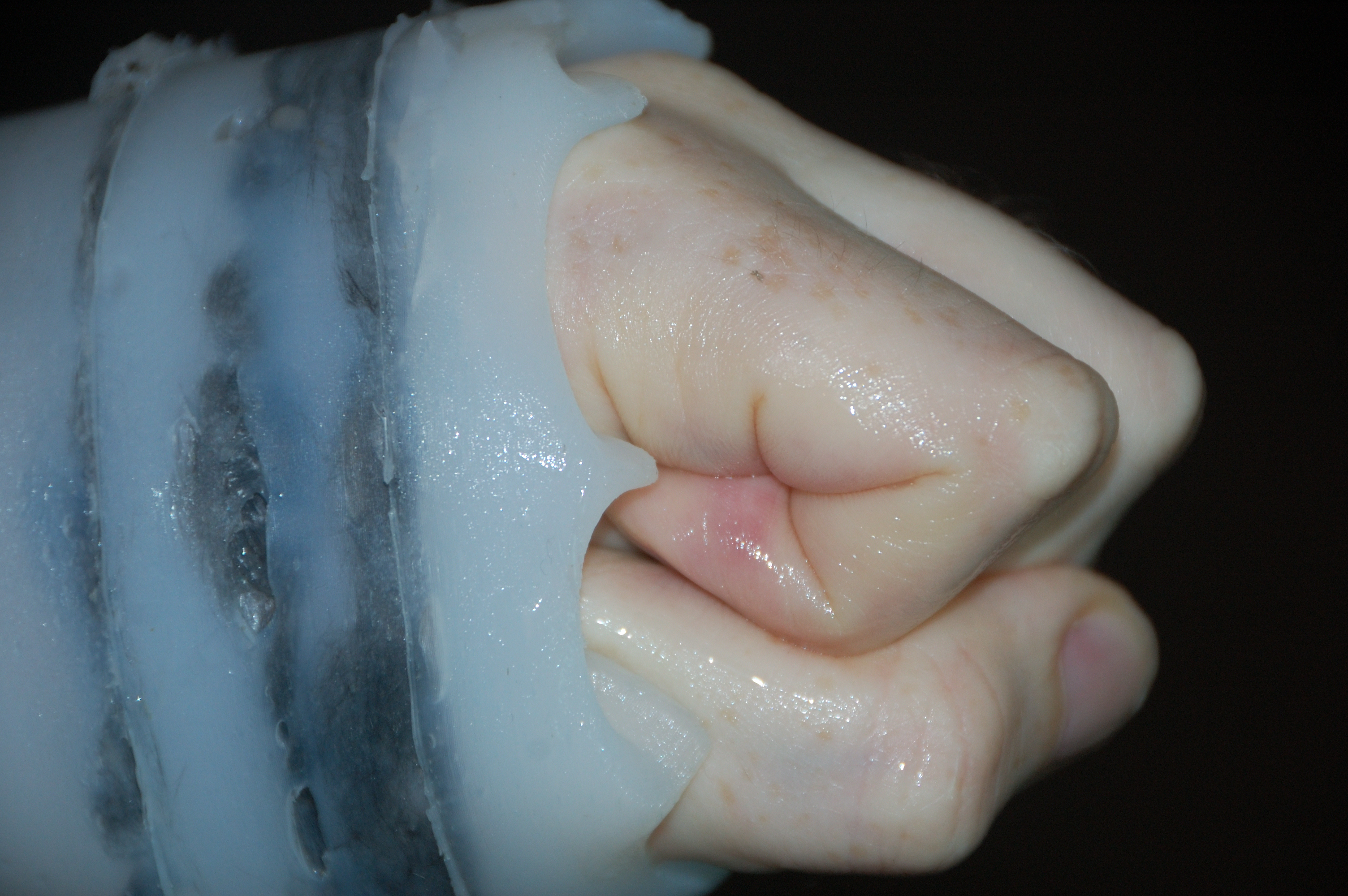
After building up the layered conductive and non-conductive silicone per my insertable design, the next challenge was getting a negative mold of a penis. My penis to be precise, because I wanted the first prototype to be of my own wang!
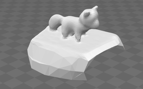
I managed to make a 3D model of a fox using 32 still images.
Turns out it’s a lot harder than you think to make a clone of your penis. I investigated doing a 3D scan using photogammetry, which could have worked but it really requires a lot more of a “still” model as it were. I did, however, get this great 3D model of a plush fox by taking 32 still images and stitching them together in 3D using freely available software.
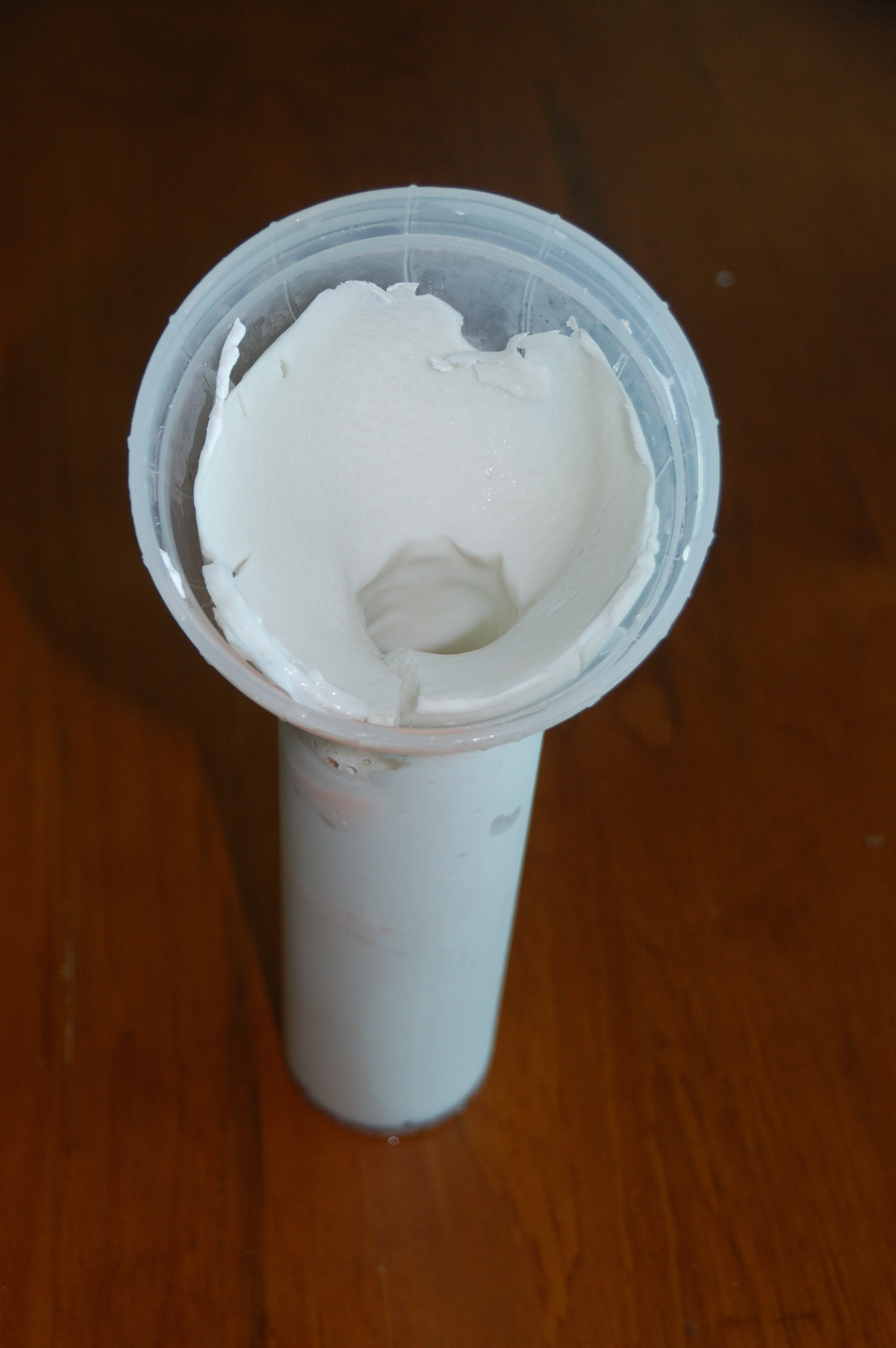
The negative penis mold life-cast with alginate.
In the end, I bought one of those “clone a willy” kits. “Casting from life” as it’s called is usually done with alginate (the same stuff that’s used to make a mold of your teeth at the dentist). It’s body-safe, non-toxic and (unlike plaster of Paris) doesn’t heat up as it sets, but it also sets rather rapidly so you have to be quick. It’s also heavily reliant on water to keep its shape so you have to keep it well hydrated. I found that filling the negative mold with water and putting it in the fridge allowed it to last longer.
You have to get the temperature of the alginate correct (32 degrees C) whilst maintaining an erection, all within 2 minutes. It took a few goes, but I managed it (with a little help).
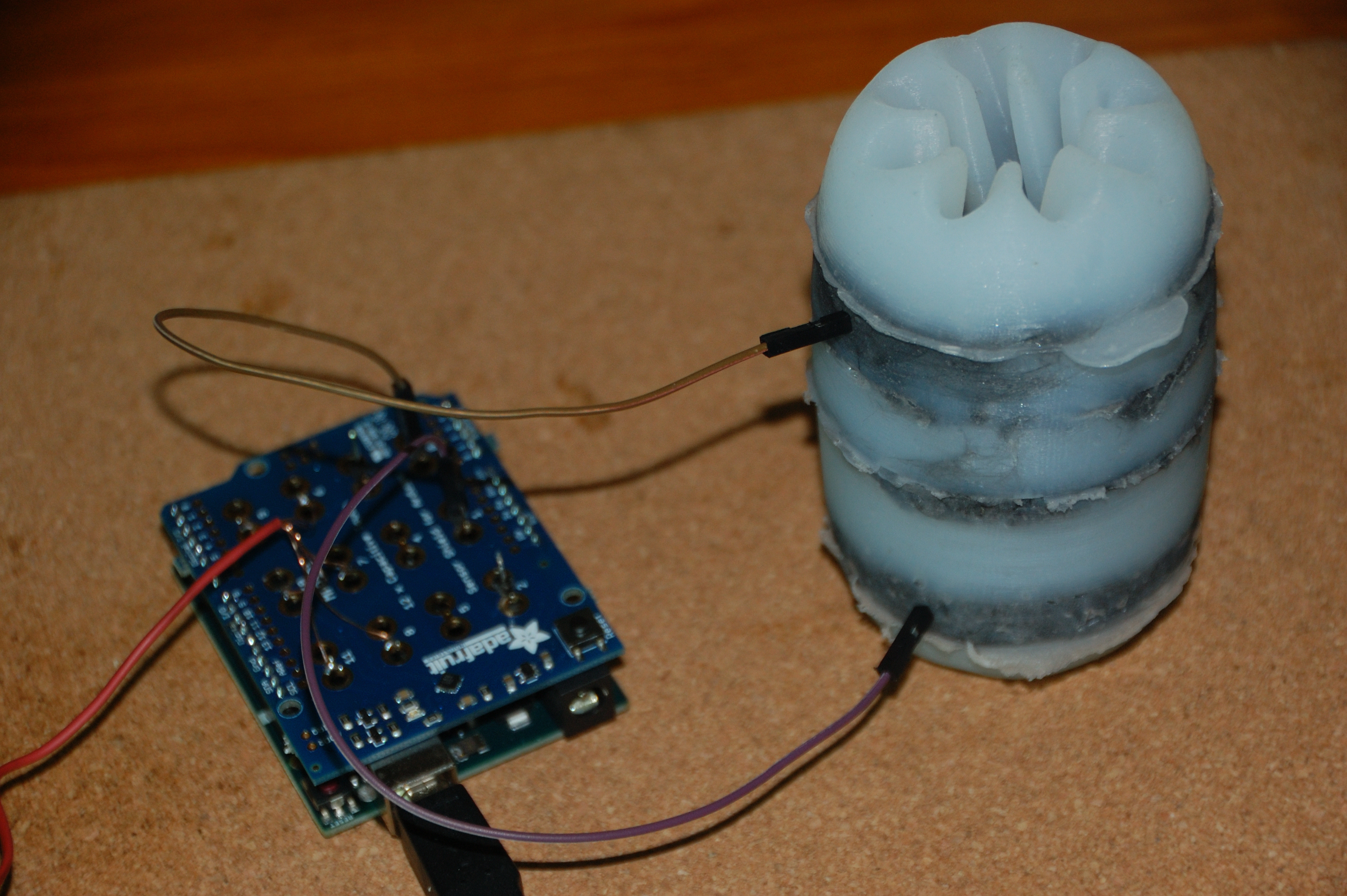
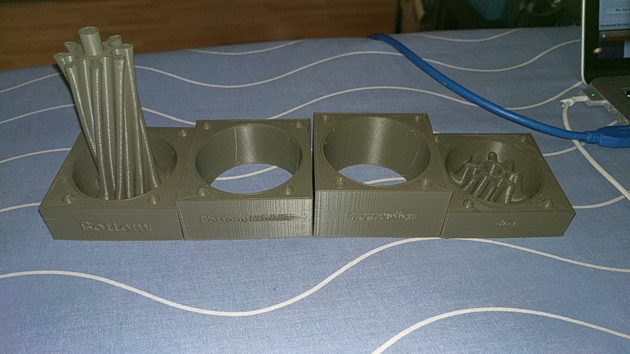
The sensing core for the insertable held together better than I expected.
The other, most important part, was getting a protective layer of silicone around the sensing apparatus because I didn’t want little carbon fibres poking people in the butt. The sensing apparatus had now developed into a rather scary looking porcupine with 8 wires coming out of it, terminated by alligator clips.
Effectively what I am trying for is a process known as overmolding, where you mold a material over another to achieve the desired effect.
The silicone that came with the “Clone a willy” kit was a harder shore value than the silicone I already had, it was also much slower to cure. For this reason, when I poured it into the negative, it just pooled in the tip and didn’t really cover the sides as I hoped. So, I used my softer, faster curing silicone to coat the inside first, filled it with the (pink) harder silicone and then rammed the sensing apparatus down the center of the mold.
To be honest, I don’t think this is entirely the best approach and will need some re-thinking.
Once I hooked up the alligator clips to pins 4 through 11 on the MPR-121 shield, I was able to output tab separated values out onto the serial port. The Arduino software I am using conveniently converts those into a graph if you like.
The insertable test script is here. Note that I overwrote the initial voltage and threshold values in a bit of a brute-force manner because I didn’t want to mess with the existing cpp files that come with the MPR-121.
I get nice clean signals when I interact with ant part of the device, cleaner than I expected. My next challenge is interpreting all this data as “gestures”. I am thinking of getting information like % insertion, speed (rpm) and the kind of activity (e.g. touch, buttsex, handjob, blowjob, lick, squeeze, etc).
I think the dynamic time warp algorithm would be ideal for this kind of processing because not only could it match gesture curves without being time-based, the amount of “time warp” I get could tell me how fast the gesture is happening.
Of course, after I have done all this work, I discovered the concept of Swept Frequency Capacitive Sensing which could actually be the ultimate answer to my challenge. I guess we’ll see how we go!
The insertable toy was the first one I thought of over a year ago. The original design involved wires and conductive paint to somehow create capacitive touch surfaces.
Original design for the insertable device – Wrong!.
I knew that wouldn’t work, not least because the exposed wires were not going to be a smart idea in the butt. With the discovery of the conductive silicone I decided that maybe the best approach would be to pour layer after layer of conductive and non-conductive silicone into a negative mold of a penis but that just created more questions, namely: how do I get the wires connected to the conductive silicone in the first place?
Original design for an inner battery holder – also wrong.
I thought about having a solid center with conductive pads on it for the shaft, the benefit of that approach would be that I could put batteries in it and such. Advice from my friends who have far more experience with toys of this nature quickly scrapped that idea, but not before I got a nice 3D model printed.
3D Molded core prototype
The design above and model to the right is of a 20mm diameter shaft with a 18mm hollow that could accept 2 AA batteries and go inside a toy. The consensus from my friends who have more experience with butt toys was that if you’re making a silicone toy, you may as well have as much of it silicone as possible.
It was as I was fiddling with some CAT 5 networking cable that I had the brilliant idea: hey, I could just stick this up your butt! The design changes from a 20 mm solid core to a flexible core about 9 mm in diameter, but how to make the layers of conductive and non conductive silicone.
The layered silicone design calls for a flexible core of cables with 10 mm of conductive silicone sandwiched between 20 mmm non conductive silicone. – Better!
I had already determined that 5 – 10 mm of non conductive silicone would be a perfect protection from the conductive silicone whilst keeping the capacitance. 20 mm made sense then as the insulating distance between layers. What I needed then was a shaft that looked like this.
As you can see, I split the conductive silicone into two “hemispheres” to allow for more accurate sensing of what is going on.
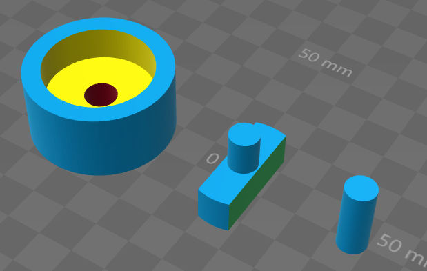
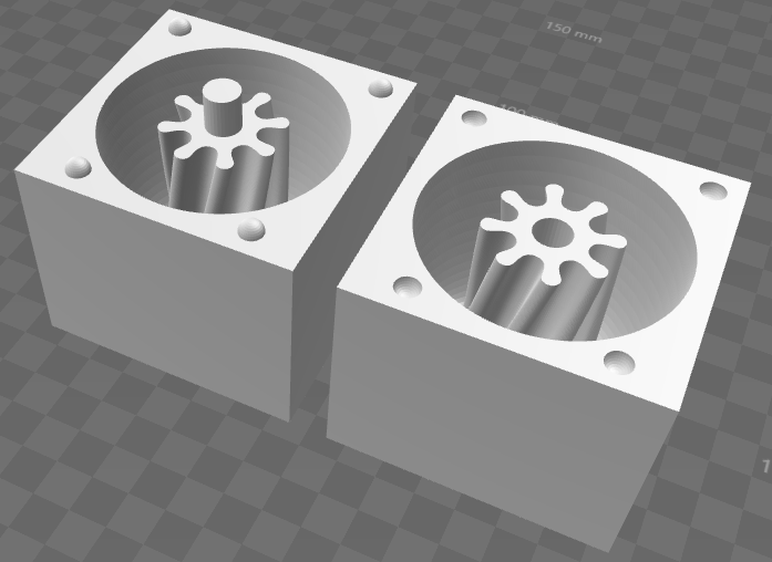
This mold design allows for the creation of both conductive and non conductive silicone layers. I call the left hand model the “O” the middle the “T” and the right is the “I”.
How then, do I get such accurate layers? Well one of my lessons from before is that silicone is best when worked additively. That is to say: adding more silicone to silicone is easy, taking it away is hard. I also learnt that pouring silicone in layers sucks.
I decided to use a mold which would allow me to create little cylinders of silicone which I could then glue together with more silicone. Behold the new design above/right. It’s made of three pieces: “O” on the left, “T” in the middle and “I” on the right.
These conductive hemispheres are 10 mm thick .
The mechanical connections are very chunky and simple, which works best for 3D printed parts. the “T” shaped piece goes into the “O” cylinder mold first, allowing you to create the two hemispheres. I found that using cling wrap on top allowed me to get a “clean” finish to the top of the layers. Also note that the conductive silicone is pretty “hairy”. I cute those hairs off easily with a pair of scissors.
Once the two hemispheres are set, you replace the “T” with the “I”, which then leaves the negative space for the non-conductive silicone parts:
Completed conductive layers threaded over CAT 5.
With the “I” piece in, the molds can also be used to make the non-conductive rings:
Making the non-conductive layers using the same process.
Putting it all together is relatively simple thanks to silicone’s ability to bond at a molecular level with other silicone. The “I” pieces were a convenient way to keep the pieces aligned so that they would set properly.
Connecting layers of conductive and non-conductive silicone.Splitting CAT 5 turned out to be a bad idea.
I tried cutting some CAT 5 cable so that I could insert that into the conductive layers, but that ended in disaster. My wire stripping skills and the need for accurate measurements meant that the wires just weren’t the right length, and I was never going to be able to stick them into the silicone with any degree of consistency, even after “tinning” the stranded wire with solder.
In the end, I used solid core wire rather than stranded wire. Solid wire sticks better into the conductive silicone anyway.
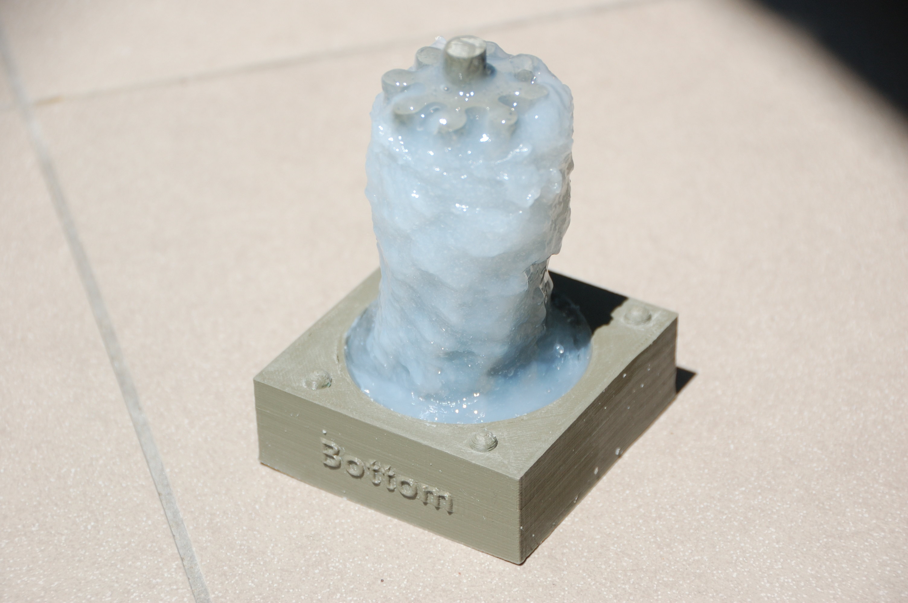
After designing the mold, it took a while for me to plan how I was going to actually use it to make my first prototype. Without further ado, this is the resulting working model for the masturbator. Your peen goes in the scary looking cavity.
The completed prototype worked better than I expected although the silicone was too hard.
The only failure of the prototype was the silicone is too hard (shore A-10) whereas it should probably be 00-30, apart from that, it worked just as I’d hoped.
I tried running silicone down the cavities in the shaft.
My first challenge was to get enough protective silicone around the central shaft of the negative model so that people’s privates would be protected. I started by trying to inject silicone into the ridges in the shaft. This was only partially successful.
Injecting the silicone didn’t seem to have any impact on the quality of contact between the mold and the silicone.
I worked non conductive silicone around the central shaft.
This was the one and only time that choosing a “fast cure” silicone helped me, because I was able to simply keep working the silicone around and around the central spiral with a plastic knife until it cured for me. The material became more and more “goopy” over time, but I found that even though it had a lumpy texture on the outside, the silicone was still filling in all the gaps properly.
The final layer of conductive silicone.
I placed the “bottom middle” piece on the bottom piece. It turns out that because ABS plastic warps a little, you have to put a fair bit of pressure on to make the pieces meet. I used insulation tape for this purpose but immediately realised that this was not the best choice. It doesn’t stick well to the ABS plastic and stretches a little.
I am glad I made the mold in parts.
Mixing small batches of silicone is very difficult. I found that it’s easier to decant the two-part silicone into two containers beforehand and use a syringe to measure a smaller amount into a mixing container. I think that in future it would be better to have a design that allowed me to mix up larger batches of silicone.
De-molding the toy was a lot harder than I expected, probably because the silicone is harder than it should be. I am glad I made it out of four parts. Perhaps in future I should make the central shaft its own 5th part, which would make disassembling the mold much easier.
Much to my surprise, once I hooked it up to a capacitive sensor, the prototype actually works. With one electrode in the device, it can pretty much tell how far a finger is in the device.
The video below shows the device detecting a finger’s depth with just a single electrode.
With two electrodes, I can get better fidelity, though I noticed that there was interference between electrodes.
I learned the following lessons from this exercise:
There’s a false economy to silicone, where you try to use less, but end up using more. There always seems to be left over silicone and you may be tempted to re-use it, but this may result in a worse outcome over all.
Silicone is best additive, that is to say, it’s very hard to remove bits off silicone once it’s been cured, but it’s very easy to add bits.
Shore A10 silicone is way too firm for the inside of a masturbator, no matter how big the cavity is, it will hurt your male bits. I think shore 00-30 would be the better bet.
Getting silicone off a rigid mold requires deforming the silicone more than you expect.
Super fast curing silicone is silly, especially if you are putting additives like carbon fibre in it. I think 20 / 30 minutes pot life (Medium) is what you want.
More than two electrodes seems to be over the top since they start interfering with each other and throwing the measurements off.
As a bonus, here’s a demonstration of just how durable silicone can be:
The masturbator is very robust to stretching and retains all its properties.
The original model would have been difficult to pour layers into.
So, my experiments in capacitive sensing have all been in aid of creating a device that can be used for interactive sex games. This post focuses on the design of a masturbator device.
In order to make a silicone device, I need a “negative” mold to pour the silicone into.
I started with a model that I discovered online, called the Helisex. It’s designed is in two parts that your pour silicone into. Once the silicone cures, you release it from the mold and you have your glorious masturbator. The twisty center piece is designed to stimulate your member when you insert it into the silicone toy.
My intention was to design something that could have layers of conductive and un-conductive silicone so I could detect how far in the dong went. The helisex design would have been very hard to layer silicone into, so I separated it into four pieces:
I split the negative mold into four parts.3D Printed mold in process using ABS plastic.
Note that since I was 3D printing these parts, there’s no way I could simply split the model into 4 equal parts, because the center piece would have nothing to connect to. I decided on the “tower in the base” approach, because that could allow me to cover the center piece in un-conductive silicone.
Conveniently, a friend of mine has a 3D printer and was able to print the models for me.
The 3D printed model came out very well, albeit a little warped.
The 3D printed objects came out very well.
I used 180 grit sand paper to sand the ridges out of the parts.
After the models were printed, I set about sanding. I had to get the top piece re-printed because I had misjudged the height of the center column by 10 mm.
I sanded every piece with 180 grit sandpaper to help get rid of the ripples that is characteristic of 3D printed parts. I then sanded with 240 grit and 400 grit. To be honest, I think the 180 grit did all of the work and the other sand paper didn’t make much difference to the result.
I resized the cavities for the nubs with a drill bit.
The little plastic nubs and cavities were built into the model to allow them to line up properly. The “Negative” cavity was invariably too small (or the nub too large) because I didn’t realise I needed about 0.5 mm clearance either side.
No matter, a drill bit and elbow grease soon fixed that problem! I took a drill bit and filed out the excess from the part. This turned out to be quite easy since the ABS plastic is relatively soft.
The drill bit went right through the part into the softer “fill” printed area.
What I didn’t realise is the “wall” of the 3D printed part is only about 1mm thick, so a little vigorous filing will easily perforate the wall of the printed part. Fortunately this was not a big deal and in hindsight, I would have probably been better off with holes for bolts anyway rather than fancy little nubs.
I learnt a few things out of this exercise:
ABS plastic warps (unlike PLA) so although ABS will last longer and is definitely safe with silicone, PLA might be a better choice if the mold parts need to fit together perfectly.
About half a millimetre of clearance is required for parts to slot into each other, this can be achieved by sanding.
Chunky mechanical connections are better than fiddly ones.
Making holes all the way through is better than a cavity part way through.
2mm is the narrowest you want to make any piece in a 3D printed object
The outer “shell” of the 3D printed part is thinner than you think and you can easily perforate it. If you do, it’s not the end of the world.
3D printed parts work well subtractive, that is to say: you can always shave something off the model more easily than adding something.
I’ll start with the result for those who don’t have time to read. With 10mm of non-conductive silicone insulating the carbon-fibre conductive silicone, we still get a pretty good change in capacitance which can be detected.
This is great news! The 10mm of non conductive silicone can act as a physical barrier whilst the conductive silicone acts as the touchable surface.
How does it work?
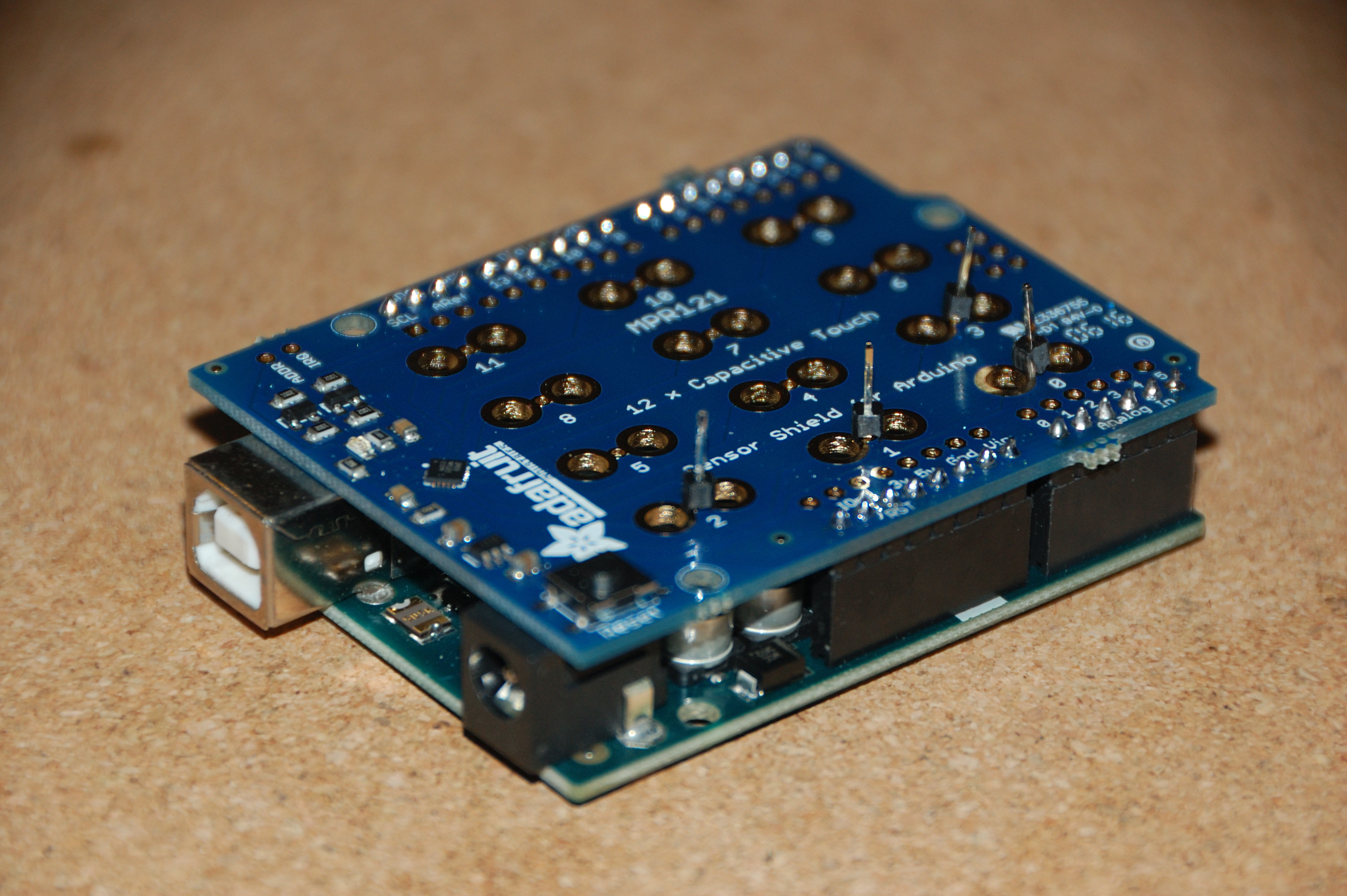
The headers have been installed on the shield.
I bought a MPR121 Capacitive touch shield for the Arduino. The first challenge I had, having never used an Arduino before, was to figure out how to assemble it. They come with little headers that you solder onto the shield, which is quite easy to do, especially if you use the Arduino as a guide (stick the long end of the headers into the Arduino’s connectors and then solder the shield onto that) just be careful not to overheat any components!
The MPR-121 shield snaps easily into place.
The Arduino and shield just snap together. It took me an embarrassingly long time to realise this because I was expecting some fancy wiring. It’s just “plug & go”.
My initial tests were disappointing: the system failed to detect “touch” whenever I touched the non-conductive silicone, but recognised a touch when I touched the conductive stuff. This is not what I wanted because as I discovered before, the conductive silicone has these little carbon fibre hairs sticking up out of it that could cause itchiness in places you really don’t want it.
I then realised that the sensor provides both baseline and filtered data. My understanding is that the baseline data is something akin to a moving average that is able to take into account noise and ambient effects (like humidity I suppose).
I found that when the sensor is touched “properly”, on the conductive silicone, the “filtered” value drops momentarily below the baseline value, triggering a “touch”. When I touched the non-conductive side, both the baseline and the filtered values drop at the same rate. This tells me that the drop is probably so small and gradual that it’s not picked up by the
My initial modified code is below:
/*********************************************************
This is a library for the MPR121 12-channel Capacitive touch sensor
Designed specifically to work with the MPR121 Breakout in the Adafruit shop
—-> https://www.adafruit.com/products/
These sensors use I2C communicate, at least 2 pins are required
to interface
Adafruit invests time and resources providing this open source code,
please support Adafruit and open-source hardware by purchasing
products from Adafruit!
Written by Limor Fried/Ladyada for Adafruit Industries.
BSD license, all text above must be included in any redistribution
**********************************************************/
#include <Wire.h>
#include “Adafruit_MPR121.h”
// You can have up to 4 on one i2c bus but one is enough for testing!
Adafruit_MPR121 cap = Adafruit_MPR121();
void setup() {
Serial.begin(9600);
while (!Serial) { // needed to keep leonardo/micro from starting too fast!
delay(10);
}
// Default address is 0x5A, if tied to 3.3V its 0x5B
// If tied to SDA its 0x5C and if SCL then 0x5D
if (!cap.begin(0x5A)) {
Serial.println(“MPR121 not found, check wiring?”);
while (1);
}
Serial.println(“MPR121 found!”);
}
void loop() {
// Get the currently touched pads
currtouched = cap.touched();
Serial.print(cap.baselineData(0));
Serial.print(“\t”);
Serial.print(cap.filteredData(0));
Serial.print(“\t”);
Serial.println();
delay(100);
return;
}
By changing the threshold values, we can change the threshold at which a “touch” and “release” are detected.
cap.setThreshholds(1, 1);
By changing the value of “Config1” we can increase the charge current of the capacitor, effectively increasing the range of values we can detect.
cap.writeRegister(MPR121_CONFIG1, 0x20); // 32uA charge current
My next test was to see what physical characteristics of my setup gave the best results. I came to the following conclusions:
Enameled magnet wire seemed like a good idea but when combined with many others of its kin, resulted in a higher overall capacitance, meaning it’s hard to detect touches.
The longer the wire is, the more capacitance it has and therefore the worse the ability to discern “touch”, the capacitance sensor will need to be as close to the conductive silicone as possible.
The more surface area of carbon fibre conductive silicone, the better the touch detection.
10mm seems to be a nice thickness of non-conductive silicone, anything beyond 20mm is too thick.
Enameled magnet wire is too narrow and not insulated enough so it has a very high capacitance.
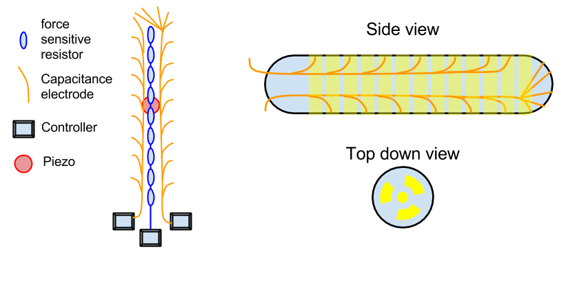
So, as part of my little teledildonics project, I think it would be useful to have capacitive sensors to determine what you’re doing with the toy.
Capacitive sensing in silicone is tricky. Silicone is a great insulator so you need to add something conductive. You don’t want anything hard in the silicone which will make it less safe to play with. I thought about using conductive paint and then layering over a layer of silicone protectant. That might still be a good option, but I worried about the durability of the paint, especially if you consider that silicone can stretch quite a bit.
Ideally, I would use some kind of “conductive silicone”. Search online for this term and you’ll probably find this instructable for conductive silicone. It piqued my interest, not least because the person who came up with the idea had sex toys in mind!
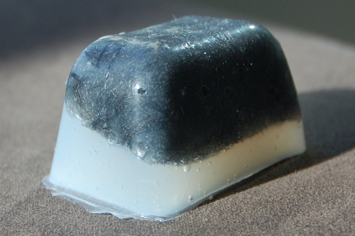
Carbon fibre strands. Each strand is only 6mm long and about 10 micrometers in diameter.
So, I set about to recreate this material myself. I had a few reservations, especially around safety. Carbon fiber is dangerous if breathed in. We don’t know the long term affects but we think they may be similar to asbestos. You can also easily cut yourself with it if you put it in a resin. So, it was with much caution that I began my experiment.
The recipe I tried is as follows:
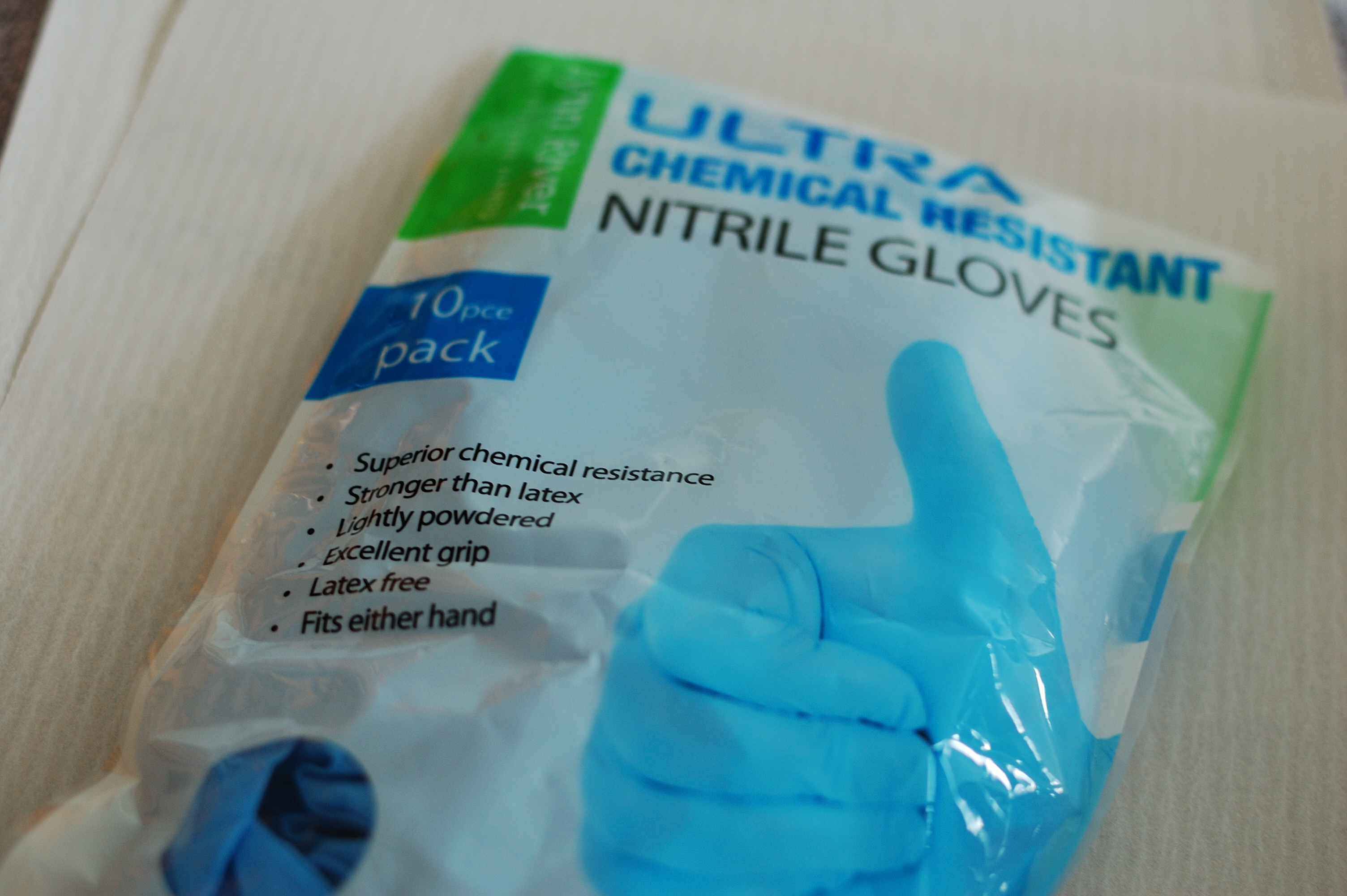
These nitrile gloves won’t inhibit the curing of the famously fussy platinum cure silicone.
Safety equipment:
Nitrile gloves – these will not prevent your Platinum silicone from curing. Anything with sulfur in it is a bad idea.
Face mask – to prevent me breathing in the carbon fibers. The jury is still out as to whether breathing this stuff causes cancer, but there’s enough research out there to say that it might.
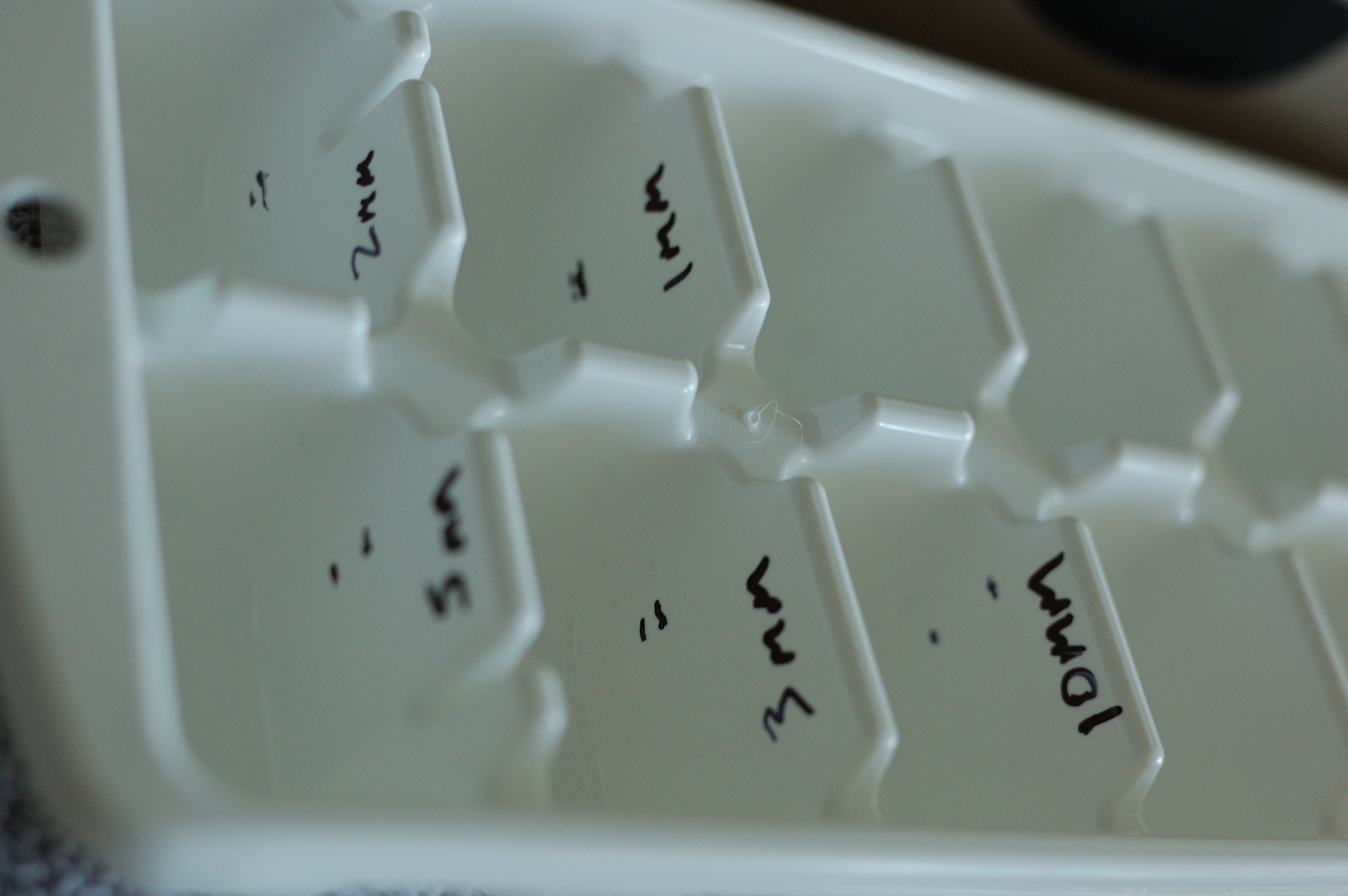
It was with visions of science that I carefully measured my molds for the silicone.
It was with visions of science that I drew little markets in my ice cube tray. I was hoping to test how much capacitance I could detect between various thicknesses of non-conductive silicone.
I took a plastic table spoon full of the carbon fibers and doused them in isopropyl alcohol. I believe the idea is the alcohol is supposed to separate the fibers and dry out fast enough so as not to inhibit the curing of the silicone. Truth be told I didn’t notice any difference in the nature of the fibers. They’re very weird to work with, they behave more like clumps of shortly cut hair than how I would imagine carbon to behave.
After all my safety precautions, I was so vigorous stirring my little mixture that I splashed isopropyl alcohol in my eye (don’t do that)! A bit of water and a visual inspection confirmed I was none the worse for wear.
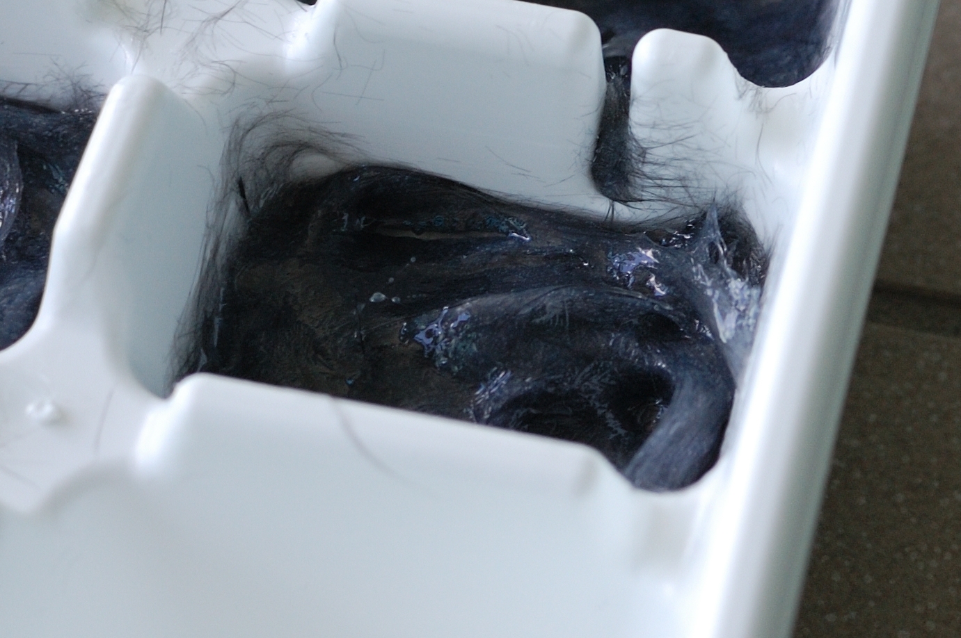
The goop was spooned reluctantly into the mold. Measurements be damned.
I then quickly moved on to making the silicone. I measured 25 ml of “Part A”, and added in 25 ml of “Part B”. I immediately regretted getting the “Very Fast” cure silicone. It started thickening pretty quickly! I added the carbon fibers (they were still pretty wet) and stirred it all like crazy.
The goop did not pour well, but spooned reluctantly into the prepared ice cube tray. The carbon fibres gave it a “stringy” quality, making it difficult (though not impossible) to work with.
It works! The silicone is indeed conductive.
Initial tests showed that the material was indeed quite conductive. The conductivity was not uniform, just like the material itself was not uniform, but it’s good enough for my purposes.
After about 30 minutes, I made a second batch of silicone, this time without the added carbon fibres and layered it on.
The material is actually quite beautiful.
Another 30 minutes later and I had some very serviceable carbon fibre / silicone “cubes”. The material itself is actually quite beautiful, it has a silvery sheen and in some places you can see the fibres swirling through the material, making for very pretty shapes. I immediately grabbed it with my hands. It didn’t feel rough or spikey as I expected, it actually felt quite soft and ductile. I stretched it.
The conductive silicone does not spring back into form as well as pure silicone, but it holds together pretty well. This resilience combined with the fact that it felt pretty safe got me feeling hopeful. Maybe the silicone effectively immobilises the carbon, making it safe?
Closer inspection proved this to not be the case. In sunlight, you can see the little carbon fibres crisscrossing each other on the surface. By pulling the material, I was also able to get some fibres to stick out.
Carbon fibre strand sticking up out of the silicone.
To be fair, the fibres are very small and will not cut you, they bend as you press them. I expect that they could cause itching, like any fine hairs. My hands feel itchy now, either from my imagination or from playing with the material. I also know that carbon fibre will break if pulled. Imagine fragments of this stuff breaking off and getting into sensitive areas?
No, if we’re going to have conductive silicone, it will need to be covered with at least 0.5 mm of normal silicone. Next test will be how much of this protective silicone I can have before the capacitive sensing stops working.
Like all real life stories, this one starts in the middle.
I have been interested in the field of teledildonics for well over a decade now. For the uninitiated, this is the technology used for sex at a distance, or even potentially entirely artificial sex with your computer.
My interest developed in a round-about way. You see, I think that haptic technology (any technology to do with the sense of touch) has a lot to offer humanity, but as with anything, no one will fund the research unless it’s sexy. How better to make something sexy than to literally add sex?
I’ve been a passive observer of the field for a while now. I admire qDot (of metafetish fame) a lot, he is something of a celebrity in the Teledildonics world having built the original “sex box” out of an XBox contoller back in 2005 and then actually worked towards it including a stint at Linden Labs.
So, why am I posting all this? Well, I am on the cusp of genius / disaster with my own little teledildonics project. I’ve decided to actually start making something. This series of posts is going to chronicle my own experiences / mistakes in this area. I hope this is of interest to you and that maybe you can learn from my misadventures.
My plan
A lot of teledildonics devices focus on stimulation. That is: how do we vibrate or move or whatever to make the user feel like they’re having a more realistic sexual experience? I am actually ignoring that altogether and want to focus just on sensing.
The reason for this is I can imagine a situation where someone is playing a game or viewing some interactive content where they are using some kind of device (e.g. a dildo or a masturbator) and the content responds to how they use the device. I think that the player would be quite willing to stimulate themselves if given the right feedback. Just look at the game edgemeplease.com. Imagine if that game actually knew what you were up to? I think it could lead to a far more immersive experience. I guess therefore that I’m not too focused on the “tele” part of the challenge and more the “dildonics”.
Anyway, welcome to this little experiment. I will post irregularly, but with enthusiasm. So kind of like sex, I suppose.